Hardware Reversing to find UART and shell
October 31, 2019
I’ve (finally) posted the follow up to my last video! In this one we’re dipping a toe into hardware reversing by finding a UART (serial port) and using it to get shell access on a 931-L. If you’ve never done anything with hardware this is a great place to start, or at least get some initial exposure to the concept.
For those who want to try this on there own I’ve posted a list of tools/equipment, a set of quick reference steps from the walkthrough, and finally some troubleshooting ideas in case you hit any snags. The camera is cheap and it’s about as soft a target as they come, so hopefully this is a fun way to cut your teeth.
Tools and Equipment
Here’s a breakdown of what we used in the video, roughly in the order it appeared. You don’t need specific makes/models of anything except the 931-L; whatever equivalent tools you have will probably do the trick.
- D-Link 931-L Camera
- Shim made from an aluminum can
- 1mm guitar pick
- Phillips head driver (PH0)
- Benchtop Vise (Panavise 201)
- Switched outlet
- Multimeter (Innova 3320)
- 3.3V FTDI (Sparkfun DEV-09873)
- Grabber Probes w/ jumper wires attached
- Header Pins
- USB cable
- Kali Linux (VM running over Mac)
Walkthrough: Quick Reference
Finding Internal Photos in FCC Filings
We needed to know if the 931-L had the kind of attack surface we were looking for (specifically a UART). To get a peek at the inside of the camera before buying it we looked at the internal photos included in the camera’s FCC filing. You can find the photos shown in the video by opening the FCC’s search tool and entering 931-L’s FCC ID: KA2CS931LA1.
Quick Tip: If you want to find the filing for a device but don’t know the FCC ID, try FCCID.io’s free search tool. It’s a lot faster/easier than trying to pry it out of the FCC’s search tool.
Cracking the Case and Prepping the Board
The camera’s case is held together with ~8 plastic clips, which we removed using a shim cut from an aluminum can and a 1mm guitar pick (there are great kits available for this kind of thing but I wouldn’t recommend investing in one for your first project).
We put the board into a benchtop vise to hold it steady, then plugged the power supply into a switched outlet. This allowed us to power the device up and down easily, without fumbling around to pull the cable out. If you don’t have a switched outlet, a surge protector or a lamp cord switch will do the trick just fine.
A bit out of order here, but one last board prep item: we also placed a row of 4 header pins into the row of plated through holes (TPHs). We didn’t solder it, but we got really lucky there. If you’re doing this on your own I’d recommend soldering them in, if only to remove a possible point of failure. It’s also worth noting that the pin size and pin pitch (distance between pins) is smaller than the more commonly sized connectors out there. If you run into problems, consider just soldering jumper wires to the PTHs themselves (to save time remember you don’t actually need the one marked V!)
Finding the UART
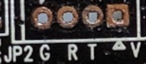
The JST connectors shown in the FCC photos weren’t on our camera, but the four plated through holes (PTHs) that the JST connector used where still present. As shown below the reference designator on the board was J2, and PTHs themselves were labeled “G”, “R”, “T”, and “V”.
Testing the UART
It seemed likely that the labels on those PTHs stood for Ground, Receive, Transmit, and some kind of voltage, but we ran a hasty survey to be sure. We began by checking for Ground on “G” by using the multimeter to run a continuity test between “G” and a spot on the board where the ground plane was exposed. With ground confirmed we switched the multimeter to measure DC voltage, powered on the device and checked the voltage levels on “R”, “T”, and “V”. Observations and conclusions from the survey are summarized below.
| Label | Observations | Conclusions |
|---|---|---|
| G | Continuity with device’s ground plane. | G = Ground |
| R | Pulled down when device running. | R = Receive (Serial In) |
| T | Jitters ~3.3V when the device is booting | T = Transmit (Serial Out) |
| V | Pulled up to 3.31, stays there. | V = Voltage (supply) |
Quick Tip: If you’ve never used a multimeter or are just a bit rusty, there are loads of tutorials out there. SparkFun’s How to Use a Multimeter is solid and includes walkthroughs of the continuity and voltage measurements we did in the video.
Wiring up the FTDI
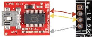
With the camera powered off, we connected the FTDI to the camera board using jumper wires and grabber probes as shown below. Note that the “V” was not connected.
Once the FTDI was wired up, we connected it to the laptop via USB.
Verifying the USB and opening a serial connection
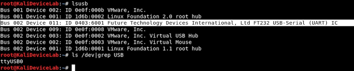
With the camera powered off, we verified that the Kali VM recognized the FTDI with lsusb. We then found the TTY for it by running ls /dev/|grep USB. Since the FTDI was the only USB device attached to the VM, it was the only game in town (USB0).
We now knew where to open the serial connection using the screen utility, but we didn’t know which baud rate to specify. While we could have calculated it or used a tool that could calculate it for us, we opted to try guessing it from a short list of common baud rates.
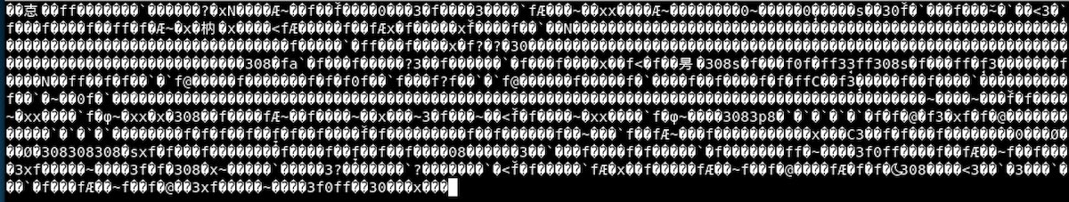
Our first guess was 115200. We tested it by opening a serial connection with screen /dev/ttyUSB0 115200, and then powering up the camera. The result was mangled output, so this was a bad guess. We powered off the camera, then exited screen with a ctrl+A+D
Next we tried another common baud rate: 57600. Again, we used screen to open a serial connection (screen /dev/ttyUSB0 57600), then powered on the camera. This time it worked! We could see the bootloader, which appeared to be unlocked.
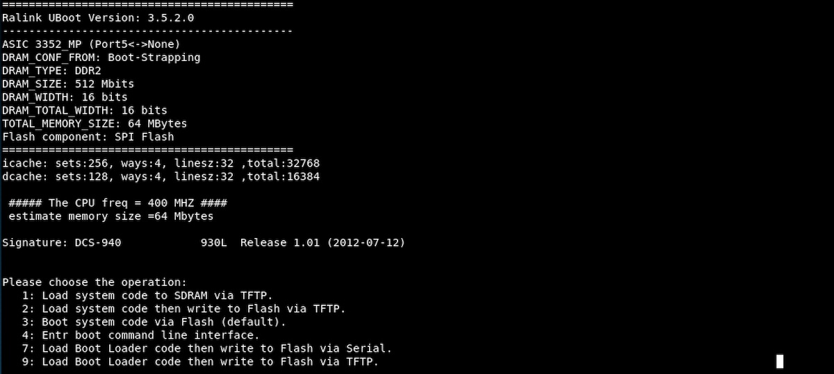
The boot process took ~3 minutes, during which a lot of information was written to the screen. We kept a copy of everything for an offline review (we used the scrollback buffer, but screen does have a native logging feature). After the console messages from the boot process calmed down we verified the shell with a few basic commands (pwd, ls, and ps -ef).
That was it for this one. Next time we’ll poke around the shell a bit and see what we can do.
Troubleshooting
A few common problems and things to try if you run into them:
Your machine doesn’t recognize the FTDI. You’ve made sure the FTDI is connected via the USB cable, but you don’t see it in a lsusb.
- If you’re running a VM, make sure the USB is connected to that, rather than your host machine.
- Depending on your OS and FTDI it could be a driver issue, check the docs for your stuff.
- If all else fails, disconnect it all, reboot, and reconnect it.
Errors when opening a serial connection. You’re getting error messages with stuff like Device Busy or Cannot exec ‘/dev/ttyUSB0’: No such file or directory.
- Screen is notorious for hanging onto devices if it’s not detached gracefully, which can cause device busy errors. Check for fouled processes with something like
ps -ef|grep SCREEN. Prevent this kind of stuff by making sure you detach fromscreenconnections with ctrl+A+D - If you’re getting no such file or directory errors, it could be that your machine isn’t recogizing the FTDI (see above), or just that you’re specifying the wrong device. Double check that TTY- it won’t always be ttyUSB0, particularly if you’ve got more than one USB device connected.
A serial connection opens but nothing happens. Sounds like your computer can talk to the FTDI (that’s good), but not beyond it.
- Check your wires, make sure the connections are good, and that everything is going to the right place.
- See the wiring diagram above for reference…mistakes like putting R-to-R are easy to make.
A serial connection opens but the output is a mess. We saw this in the video when the baud rate was wrong, so that’s an easy thing to check. But assuming that’s right:
- Triple-check (srsly) your ground connection- especially if “everything was working fine last time”. A bad ground can foul up all sorts of stuff, and is often the source of connections looking janky/missing information.
Camera isn’t booting or is otherwise being weird
- Check your connections to ensure you’re not accidentally shorting anything. A bit too much solder or a bad angle on a grabber probe is usually the culprit.
- If you’re still having trouble after that try the factory reset process (see camera docs).
- It’s also possible that your board became damaged at some point, but fixing stuff like that is beyond what a beginner should try to fix.